Operating Instructions
1. System Setup
Instructions here are generalized as much as possible. Several schematic example setups illustrate the tubing connections and some potentially interesting experimental configurations.
General Guidelines
The inlet/outlet pumps, media reservoirs, and fluidic tubing upstream of culture plates should be kept in the culture incubator with the perfusion plates to avoid degassing in the tubing.
Skimmer pumps, FETbox(es), and the waste reservoir can be placed exterior to the incubator.
Note
Minimize fluid head for the outlet and skimmer pumps as much as possible for maximum performance.
Preheat the inlet/outlet peristaltic pumps in a dry incubator/oven several degrees higher than the final target temperature. This will minimize formation of potentially damaging condensation on the electronics and mechanical components.
Sterilization & Priming
Sterilization is done in-place, without plates connected. Use a straight barbed fitting at the point in the tubing where the plate will eventually be connected. This joint can be easily split and connected directly to the tubing already connected to the plate.
Connect a 70% EtOH bottle to all reservoir connections.
Disengage the outlet pump tubing from the pump rollers, such that the inlet pumps can pump freely all the way to the waste.
Run the inlet pump at full speed until at least several volumes have passed through all of the tubing.
Important
If using pinch valves in the circuit, cycle their positions regularly to ensure full EtOH contact.
Disconnected EtOH reservoir, and connect the inlet tubing to all culture media reservoirs.
Repeat (3) with media to purge EtOH from the system and prime the tubing with culture medium.
Note
If multiple reservoirs are utilized, take care that the line downstream of the valves contains the correct medium for the start of the experiment.
Engage all peristaltic pump head to prevent backflow and avoid spillage when connecting the perfusion plates later.
Sterilize the skimmer tubing by pumping 70% EtOH through, then run dry to clear. Wrap exposed tubing ends in sterilized aluminum foil until ready to connect to the perfusion plate.
Perfusion Plate Connection
Seed an Nunc OmniTray plate with the desired tissue culture model. Allow cells sufficient time to adhere prior to initiating flow.
In the tissue culture cabinet, place the assembled and sterilized perfusion lid onto the seeded plate base. Verify that the inlet/outlet nozzles sit below the media surface and do not ride on the culture surface.
Transfer the assembled perfusion plate to the incubator.
Split the tubing at the joint described in Sterilization & Priming. The barbed fitting should remain on the outlet side.
Connect the outlet pump tubing to the plate outlet tube, and press fit the bare inlet tubing into inlet P200 nozzle.
Connect the skimmer tubing by pressing it ently into the clamped skimmer P200 nozzle.
The system is now ready for operation.
2. Inlet/Outlet Flow Rate Delta
The “skimming” approach we’ve taken to plate volume regulation requires a slightly higher inlet flow rate than outlet flow rate, with the excess removed in a controlled way by the skimmer system. The inlet/outlet flow rate delta should be kept as small as possible to minimize volume fluctuation.
To determine a safe operating flow rate delta, variability of the inlet/outlet pump flow rates between pumps and/or channels is measured. This can be done in parallel with calibration. The exact method for calibration is model/manufacturer specific, but generally a flow rate in the intended operating range is set, run for a fixed period of time, weighed, and the theoretical vs. measured dispensed volume is used to set the calibrated flow rate. A safe flow rate delta takes into account variability between pumps, tubing, and channels. A safe margin is ~1.5-2x the measured flow rate range.
If re-calibration between pump tubing replacement is undesirable, variability in different stoppered tubing can also be considered and accounted for in the flow rate delta. For example, below, four different pump tubes were tested randomly across the four channels of two different Ismatec Reglo Digital pumps. In this case high variability is observed and an inlet/outlet flow delta of ~10% would be considered a safe operating margin.
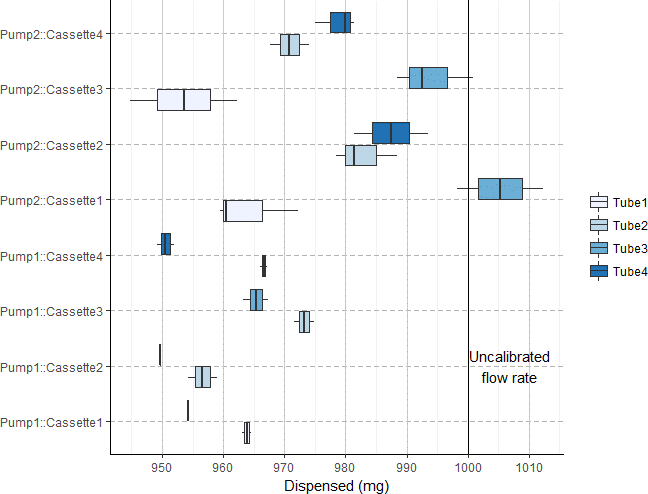
Measured dispensed volume of random combination of two pumps and four sets of stoppered tubing. Cassettes (sping arm for clamping stoppered tubing down against the rollers) were kept with their original pumps. n = 3 for each data point.
3. Skimmer Pump Operation
Skimmer pumps do not need to be run continuously. Excess medium accumulates slowly (hours to days) and can therefore be removed intermittently to reduce power consumption and wear on the skimmer pumps/tubing.
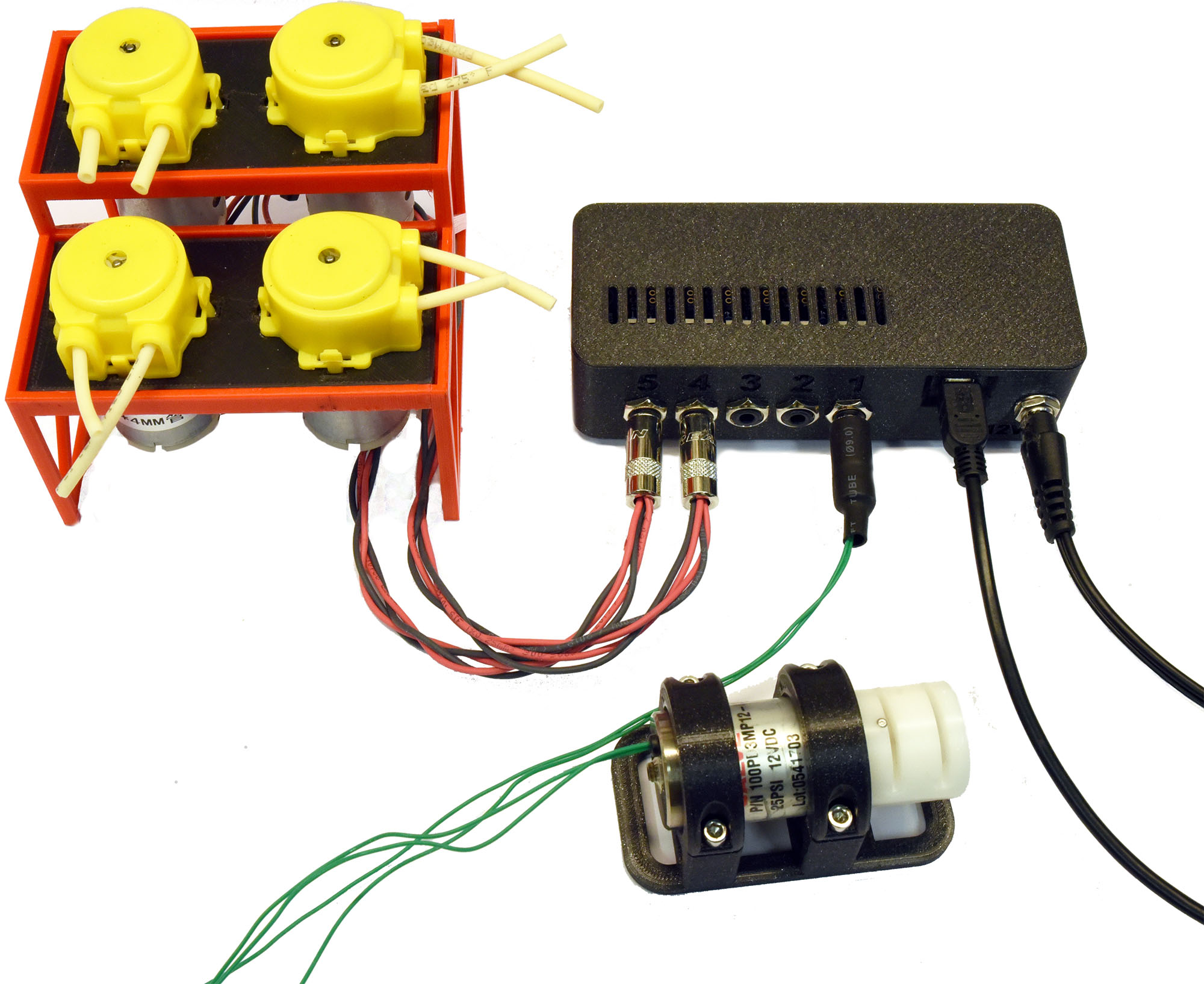
DC peristaltic pumps (wired in 2x banks of two) connected to a FETbox for use as skimmer pumps (upper left). Pinch valve also pictured (lower right).
When using DC peristaltic pumps controlled by the FETbox, as above, the PlateFlo scheduler module can be used to run the pumps at regular intervals as below, for example:
>>> from plateflo import fetbox, scheduler
>>> from datetime import datetime, timedelta
>>> from time import sleep

>>> # autoconnect to FETbox
>>> fet = auto_connect_fetbox()[0]

>>> # create scheduler
>>> sched = scheduler.Scheduler()

>>> # define skimmer start/stop functions. e.g. skimmers on channels 4 & 5
>>> def run_skimmers():
>>>   fet.enable_chan(4)
>>>   fet.enable_chan(5)

>>> def stop_skimmers():
>>>   fet.disable_chan(4)
>>>   fet.disable_chan(5)

>>> # schedule recurring skimmer events, run for 1 minute every 3 hours
>>> interval = timedelta(hours = 3)
>>> runtime = timedelta(minutes = 1)
>>> event_skim_start = scheduler.RecurringEvent(interval = interval,
>>>                                             task = run_skimmers)
>>> event_skim_stop = scheduler.RecurringEvent(interval = interval,
>>>                                            task = stop_skimmers,
>>>                                            delay = runtime)
>>> sched.add_event(event_skim_start)
>>> sched.add_event(event_skim_stop)

>>> def main():
>>>   sched.monitor()
>>>   sleep(1E-6)

>>> if __name__ == "__main__":
>>>   try:
>>>      while(1):
>>>         main()
>>>   finally:
>>>      fet.kill()
4. Example Perfusion Setups
Single Plate, Single Reservoir Culture
The most fundamental PlateFlo perfusion setup. A single plate is perfused from a single reservoir with a FETbox controlled skimmer pump for plate volume control.
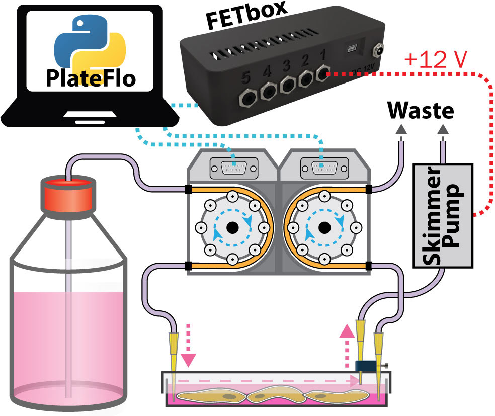
Single plate, single reservoir perfusion setup.
Tip
Inlet/outlet pumps can be run continuously, or intermittently (to reduce culture medium usage, for example) depending on the requirements of the system under study.
Dual Reservoir Sequential Flow Culture
Two media reservoirs are selected by a pinch valve (for e.g. glucose stimulation) programmatically using a FETbox and PlateFlo Python package. In addition to the standard inlet & outlet pumps, a third shared pump channel acts as the outlet pump for plate 1, pumping directly into plate two.
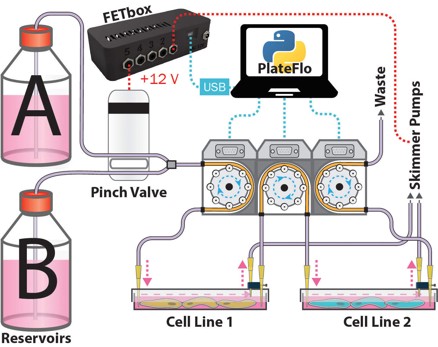
Dual reservoir, dual sequential culture plate perfusion system.
Note
In this configuration, the inlet/outlet flow rate delta is maintained across all three pumps. I.e. flow rate 1 > 2 > 3, from left to right.
This setup could be of use, for example, when studying the effect of subjecting cell line 2 to secreted factors from cell line 1 upon stimulation with small molecules from reservoir B. Similarly, it may be used for development of co-culture differentiation protocols.
5. Appendix
Selecting Skimmer Height
The following standard curve can be used to as a guide select a height block for the desired plate volume. 1.6 mm is a good starting point at ~10 mL media in the plate.
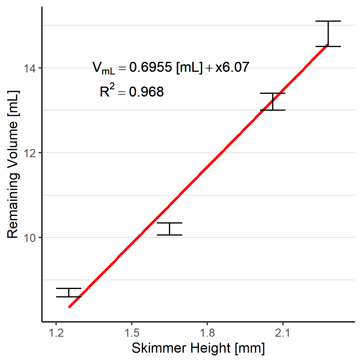
Plate volume vs. skimmer nozzle height standard curve. Determined by weight. Mean +/- standard deviation, n = 3.
1.2, 1.4, 1.6, and 1.8 mm height blocks are provided in the design files as
skimmer_height_block_<height>mm.stl. See the
build guide for
instructions on setting the skimmer nozzle height.
FETbox Serial Commands
If integration with other software, manual control, or otherwise use of the FETbox Serial Control Python module is not suitable, the serial command structure is outlined here.
- FETbox serial commands have the following structure:
@<CMD><BODY>\n
|  |    |    |
|  |    |    Line feed (LF)
|  |    |
|  |    Command body, arbitrary length/contents
|  Command code, single ASCII character
Command start
Serial Command |
Response |
|
|---|---|---|
Get Device ID |
|
|
Heartbeat |
|
|
Enable Channel |
|
|
E.g. Chan 2 on: |
||
Disable Channel |
|
|
E.g. Chan 4 off: |
||
PWM Channel |
|
|
E.g. Chan 3 to 80: |
||
Hit-and-Hold |
|
|
E.g. Chan 5 hold 55: |
||
Digital Read |
|
|
Analog Read |
|
|
E.g. read pin ‘A0’(aka 14): |
E.g. |
|
Digital Write |
|
|
E.g. Pin D4 HIGH: |
||
Analog Write |
|
|
E.g. Pin D5 to 155: |